How GNSS Works
Contents
1. Introduction
Global Navigation Satellite Systems are satellite ensembles which allow to any user on or near the Earth (as for example an aircraft or a low altitude satellite) to determine its position with a precision from some meters to some centimeters (more details in the "GPS, GLONASS, Galileo,..." Tutorial).
Each system (GPS, GLONASS, Galileo, COMPASS, ...) consists of a set of satellites (a constellation) which send a continuous signal towards the Earth. The atomic clocks onboard the satellites are all synchronized thanks to a reference time scale defined by the system, so that the signals coming from the different satellites of the same constellation share the same reference time scale. The user wanting to use GNSS to determine its position must have an antenna that receives the signals coming from the satellites, and a receiver that translates these signals. The antenna position will be deduced from the measurements of the time delay between the emission time (satellite) and the reception time (receiver) for at least 4 signals coming from different satellites.
2. In the Ideal World
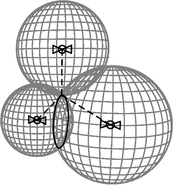
Figure 1: Location determination
based on intersecting spheres.
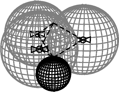
Figure 2: Using the Earth
as the fourth sphere.
In an ideal world, without noise, drift or errors, observing the propagation delay of a signal from four satellites would allow determination of the exact location of the antenna. The measurement of the propagation delay of a signal between a transmitter antenna on board of a satellite and the receiver antenna on Earth reveals the distance between both, as the speed at which the signal travels, namely the speed of light (approximately 300 000 km/s), is known.
Knowing the distance to one satellite, the receiver antenna location surely lies on a sphere around the satellite with radius equal to the measured distance between that satellite and the receiver location. Knowing the distance to two satellites, the receiver antenna location must lie on the intersection of the spheres with known radii around both satellites. This will in the general case be a circle. With the distance to a third satellite, a third sphere can be determined that will, in the general case, intersect the circle in exactly two points. (In the special case were the three satellites and the user location are coplanar, these two points collide.) A fourth satellite will allow selectioning the correct one out of the set of two points found earlier. This is the receiver antenna location that was to be determined. The geometry is displayed in Fig. 1 beside.
If a user is on Earth, the Earth blocks the signals from satellites that are below the user's horizon. In this case, the geometry of Fig. 1, with a nice spatial distribution of satellites around the user, is too optimistic. The user will only see satellites in the half space above. This implies, however, again in the ideal case, that three satellites would result in two intersection points, of which one close to the Earth's surface and the other way above the Earth. If then the assumption is made that the user is on the Earth's surface, again one of the set of two points can be discarded. Mathematically this boils down to using the Earth's surface as the fourth sphere, as is illustrated by Fig. 2.
3. In the Real World
3.1 Problems
In order to be able to determine the propagation time of a signal from the satellite transmitter to the user's receiver, the satellite message contains the time of transmission. This however requires that the receiver has a very stable and precise clock that is, moreover, synchronized to the time scale used on board the satellites. In the real world, this is not the case.
In order for the receiver to be able to determine the centers of the spheres, the satellite navigation message also contains the satellite position at the time of transmission. This, again, requires that the satellite can determine its exact position, which is, in the real world, not the case.
In the real world, the signal does not travel in vacuum, but passes through the ionosphere and the troposphere. Hence in some parts of the signal path, the signal speed will be slightly lower than 300 000 km/s. The actual mean speed of the signal when traveling from satellite to receiver is difficult to predict and moreover depends on the actual signal path. More details on the influence of the atmosphere can be found in the Atmosphere tutorial
Obviously wave refraction due to differences in Refractive Index along the signal path, or even reflections, cause the satellite-to-user distance to be wrongly determined. Moreover, this can give rise to signals that have followed different paths all arriving at the receiver, designated as multipath propagation.
3.2 Solutions
In the real world, it can not be supposed that the receiver has a stable and accurate clock that is synchronized with the time frame used by the GNSS constellation. Consequently, the measured propagation time will differ from the real propagation time by the clock difference between the user and the satellites. As the speed of light is considerable, even an error as small as 1 ns made by the receiver when determining the time, results in an error of 30 cm in the radii of the spheres. This complicates location determination, as, in general, it causes the four spheres not to intersect in a single point. Calculation of a receiver clock correction can, however solve this issue, as it would allow determination of the receiver time for which all four spheres intersect at a single point.
When the fact that the satellite positions are not exactly known, is taken into account, even with the correct propagation time of signals from four satellites, it is found that the spheres will not intersect in a single point. To overcome this issue, the distance to as many satellites as possible is measured, and a least square fitting is calculated to determine the most likely position (and time) based on the propagation times from all observed satellites.
Due to variable delays in ionosphere and troposphere, this fitting would however still use values for the radii of the spheres that are too large, resulting in an error in location determination. Therefore, the traveling times should be corrected for the variable speed in the ionosphere and troposphere, as explained in the Positioning and Timing tutorial.
4. How a GNSS Receiver Works
As the communication signals of all satellites are received by a single antenna, the receiver has to split up the antenna signal into several identical copies. From each of the copies, a navigation message, and its propagation delay, from a different satellite will be extracted. For cost reasons this splitting is performed after down conversion. This way the receiver only needs a single (expensive) mixer (per frequency band).
After down conversion of the Radio Frequencie (RF) signal to a lower Intermediate Frequency (IF), the signal is digitized by an Analog to Digital Converter (ADC). This digital signal can easily be reproduced to feed the distinct signal processing chains that will each search for the navigation message and propagation delay of a different satellite. Contemporary designs have about 100 such chains, referred to as channels in the receiver specifications.
In one such channel, the signature of a certain satellite is looked for in the data stream. If this signature is not found, the signature of another satellite is tried. Due to a Doppler shift, that is not predictable if receiver position is unknown (which can be expected for a GNSS receiver, the purpose of which is to determine a position), this signature matching is processing intensive. For that reason the process is implemented on an Application Specific Integrated Circuit (ASIC). This is the main obstacle to Software Defined Radio (SDR) implementations of GNSS receivers.
Once a certain satellite signature is found in a channel, the demodulator in that channel can be initialized to decode the navigation message of that satellite. The channel is then said to be locked onto that satellite. All channels will try to lock on to a different satellite.
To be able to decode the navigation message in a certain channel, amongst other things, the last down conversion step from IF to baseband should be performed. This is done via a digital multiplication, as the signal already passed the ADC. The frequency and phase settings of the numerical oscillator used for this final conversion step, can be used to increase the precision of the location determination.
Consequently, in addition to the measured traveling time and the information in the navigation message of the satellite, decoded by the channel demodulator, the channel also passes its oscillator settings to some other digital logic that will determine the receiver's position.
If due to some discontinuity the numerical oscillator temporarily looses synchronization with the received signal in a channel, the settings before and after this loss of lock can not be compared, due to a possible difference of an integer number of cycles, designated as cycle slips. Indeed, as a carrier signal is a periodic signal, any delay determination is ambiguous for an integer number of periods. Hence, on loss of lock, the procedure to enhance location determination with frequency and phase information deduced from the channel settings must be reinitialized.
A block diagram of a generic GNSS receiver is depicted in Fig. 3. Most receivers have a display to depict status or location information, as well as a communication port to connect the device with a PC. On Fig. 4, a photograph of an old Rogue receiver, all blocks can be found.
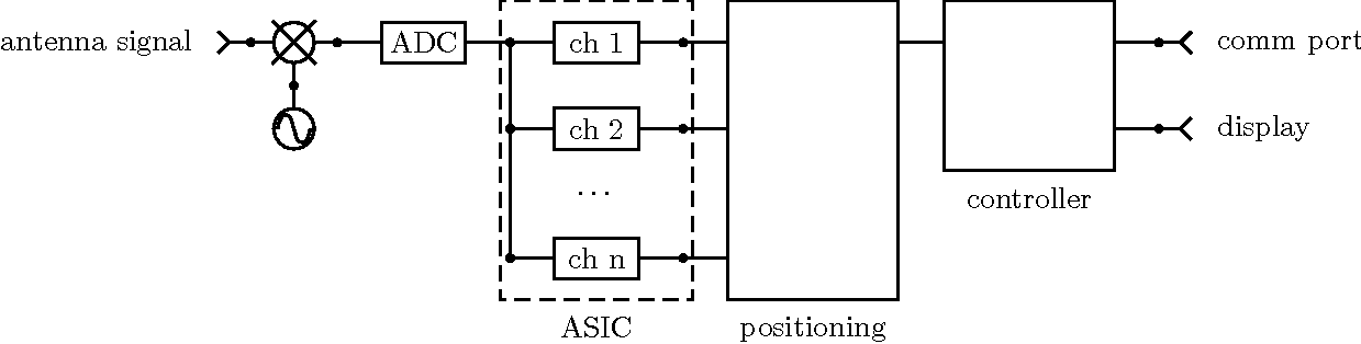
Figure 3. Block diagram of a generic GNSS receiver.
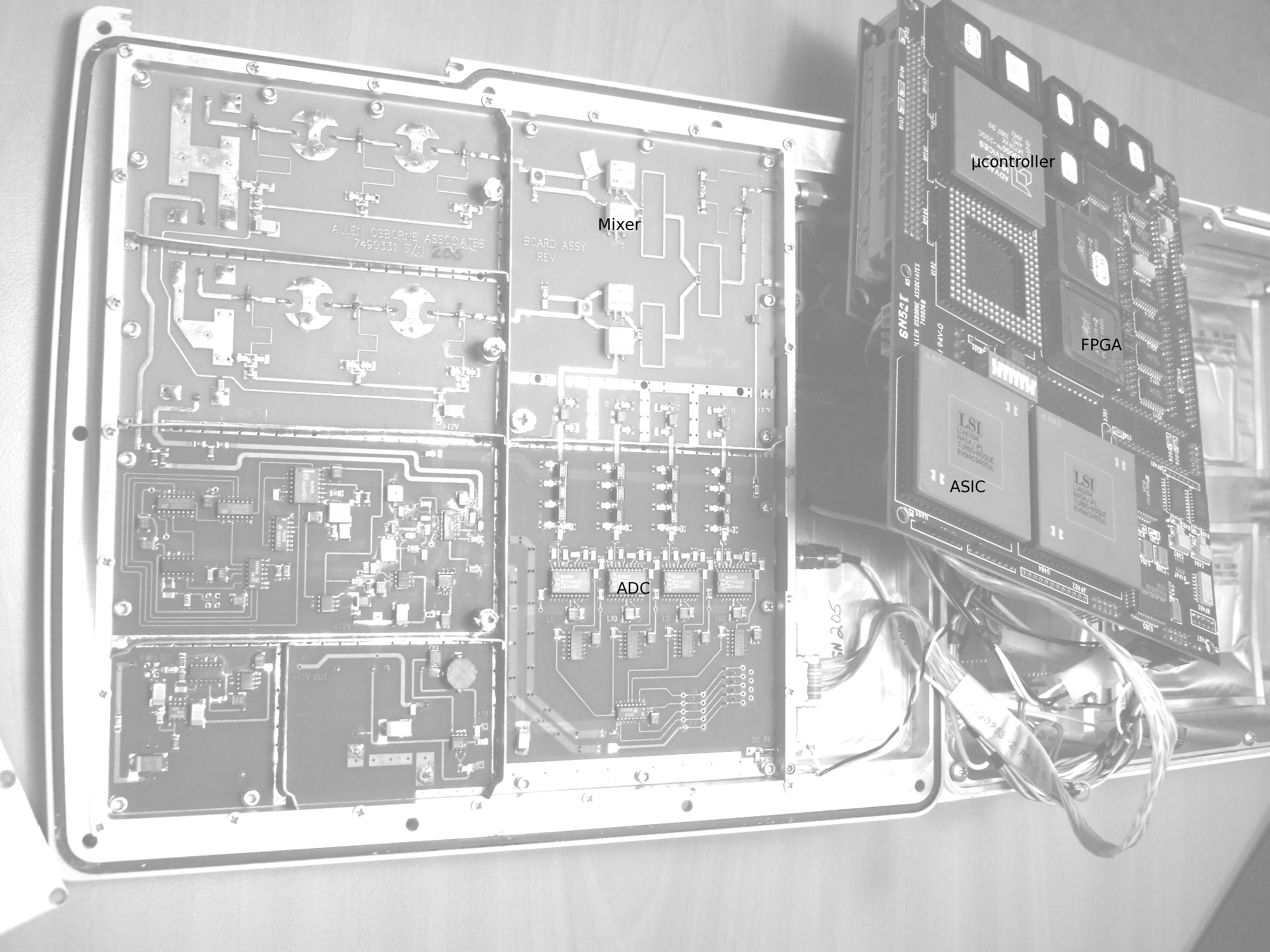
Figure 4. Photograph of an old GNSS receiver.