Coordinate Systems
Contents
2 Reference System and Coordinates
3 Reference Systems commonly used in Geodesy
3 Bibliography
1. Introduction
One of the ultimate goals of space geodesy is to estimate point positions on the Earth surface as accurately as possible. Meanwhile, point positions are not absolute quantities and then have to be determined with respect to some reference. We refer to terrestrial reference system (TRS) as the mathematical object satisfying an ideal definition and in which point positions will be expressed. Nevertheless, the access to point positions requires some observational means allowing their link to the mathematical object. We therefore call a terrestrial reference frame (TRF), a physical materialization of the TRS, making use of observations derived from space geodesy techniques. The distinction between system and frame is then subtle since the former is rather invariable and inaccessible while the latter is accessible and perfectible [Altamimi et al. 2002]. The general purpose of a TRF is to define coordinate systems in which points of the Earth are only slowly changing, and to describe the motion of any object of the Earth's environment (such as an artificial satellite).
2. Reference System and Coordinates
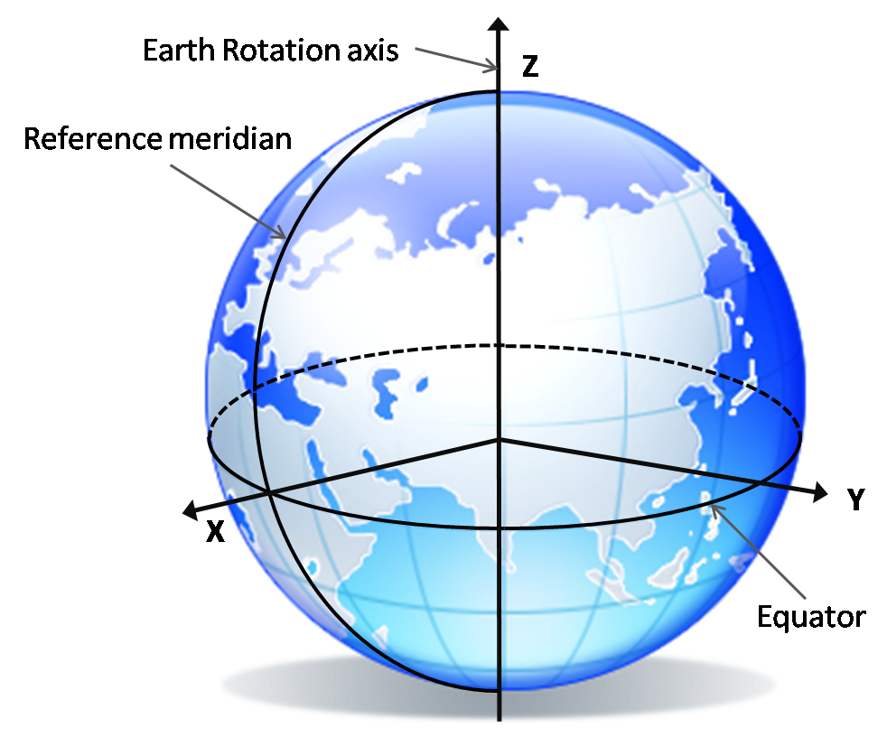
2.1 Reference System in Geodesy
A Terrestrial Reference System (TRS) is defined as a tri-dimensional reference frame close to the Earth and co-rotating with it. The origin O is close to the geocenter and the 3 axes Ox, Oy, Oz are mutually orthogonal to each other. The axes Ox and Oy are in the equatorial plane and the direction of the Z axis is close to the Earth's rotational axis.
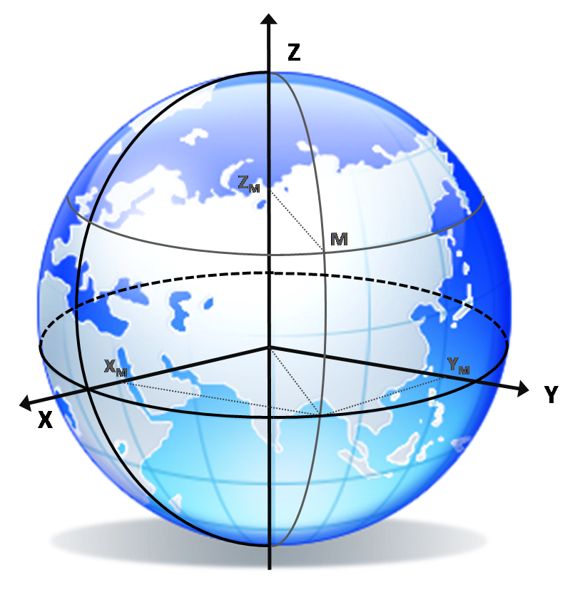
2.2 Cartesian Coordinates
Cartesian coordinates indicated by (X,Y,Z) are widely used in scientific applications but they are not convenients for end-user applications. For these applications, geographic coordinates are preferred because they are more explicit.
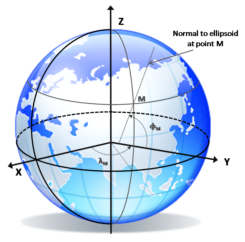
2.3 Geographic Coordinates
Reference ellipsoids are used as a preferred surface on which geodetic computations are performed and point coordinates such as latitude and longitude are defined. For this purpose it is necessary to identify a zero meridian. The longitude (&lambda) measures the rotational angle between the zero meridian and the measured point. The latitude (&phi) is the angle between the equatorial plane and a line that is normal to the reference ellipsoid. The ellipsoidal height (h) is the distance above or below the ellipsoid, positive if above the ellipsoid.
3. Reference Systems commonly used in Geodesy
Different reference systems are commonly used in geodesy:
- International Terrestrial Reference System (ITRS)
- World Geodetic System 84 (WGS84)
- and in Europe, the European Terrestrial Reference System 89 (ETRS89)
3.1 The International Terrestrial Reference System (ITRS)
ITRS: International Terrestrial Reference System
The International Astronomical Union (IAU) and the International Union of Geodesy and Geophysics (IUGG) established the International Earth Rotation Service (IERS) in 1987. The IERS began official operation on January 1st 1988. One of the primary objectives of the IERS is to provide the International Terrestrial Reference System (ITRS). The ITRS definition fulfills the following conditions:
- The origin coincides with the geocentre of the Earth's masses including oceans and atmosphere,
- The unit of length is the meter (SI),
- Its orientation was initially given by the Bureau International de l'Heure (BIH) orientation at 1984.0.
- The time evolution of the orientation is ensured by using a no-net-rotation condition with regards to horizontal tectonic motions over the whole Earth.
ITRF: International Terrestrial Reference Frame
In practice, the International Terrestrial Reference Frame (ITRF) is the realization of the ITRS. It is a result of a combination of global terrestrial reference frames (station positions and velocities) provided by the main space geodesy techniques:
- VLBI (Very Long Baseline Interferometry), the International VLBI Service (IVS), more about VLBI,
- GPS (Global Positioning System), the International GNSS Service (IGS), more about GPS,
- SLR (Satellite Laser Ranging), the International Laser Ranging Service (ILRS), more about SLR,
- DORIS (Doppler Orbitography and Radiopositioning Integrated by Satellite), the International DORIS Service (IDS), more about DORIS.
This reference system is unquestionably the most accurate (a few centimeters) used worldwide.
Various ITRSrealizations exist, called respectively ITRF88, ITRF89,..., ITRF2000 and ITRF2005. Each of them is an improvement with respect to the previous ones: more stations have been included and longer observation periods are used in order to obtain more reliable station positions and velocities. Each ITRFyy can be transformed into any other realization using a 14-parameter similarity transformation model whose parameters are made available by the IERS.More information about 14-parameter similarity transformation model.
Transformation Parameters between ITRF2005 and ITRF2000.
Transformation Parameters between ITRF2000 and previous solutions.
The reference ellipsoid associated with recent ITRF is the Geodetic Reference System of 1980 (GRS80) ellipsoid (with a=6378137 m, 1/f=298.257222101 [Moritz, 1980]).
ITRF2005
The previous ITRFyy, called ITRF2005 [Altamimi et al., 2007], was issued in 2007.
It comprises about 608 stations located at 338 sites distributed all over the world.
More than 100 of these sites are located in Europe from which one is in Belgium.
The ITRF2005 provide for each station the positions, the velocities and the timeseries of the station position residuals. These velocities reflect the effect of the crustal motion and can be used to estimate present day tectonic plate motion and ground deformations.
ITRF2008
The last ITRFyy, called ITRF2008 [Altamimi et al., 2011], was issued in 2010. Compared to ITRF2005 the major improvment is that the four individual solutions VLBI, SLR, GPS and DORIS are reprocessed solutions. The ITRF2008 network comprises 934 stations located at 580 sites, with 463 sites in the northern hemisphere and 117 in the southern hemisphere.
As the ITRF2005, the ITRF2008 also provide for each station the positions, the velocities and the timeseries of the station position residuals.
3.2 The World Geodetic Reference System 84 (WGS84)
The World Geodetic Reference System 84 (WGS84) has been established by the US National Imagery and Mapping Agency (NIMA) and the US Department of Defense (DoD).
The initial realization of WGS84 was purely based on positions computed based on observations from the Transit satellite system and was only accurate at the one to two meter level.
Over the last 15 years, the quality of the successive realizations of the WGS84 has been considerably improved.
- A first step towards more consistency between the WGS84 and ITRS took place in 1993 when the complete WGS84 network was recomputed with respect to 8 GPS stations fixed to their ITRF91 position [Swift, 1994]. This realization is known as WGS84 (G730), "G730" indicates its official implementation on GPS week 730 (Jan. 2, 1994). The WGS84 (G730) realization is consistent with the ITRF92 at the 10 cm level [Malys, 1994].
- Further improvements to the tracking station coordinates in 1996, led to WGS84 (G873). This realization consists of 13 sites (NIMA and Air Force sites); only one of them is located in Europe, namely in the UK [NIMA, 2000]. The WGS84 (G873) coordinates are consistent with the ITRF94 at a level better than 5 cm [Malys, 1997].
- In January 2002, a third improvment occured. 10 days of GPS data from 51 stations (16 NIMA + 38 IGS) were used. The WGS84 (G1150) coordinates are consistent with the recent ITRF at a level better than 5 cm.
The WGS84 ellipsoid (a=6378137 m, 1/f=298.257223563) is identical to the GRS80 ellipsoid at the millimeter level.
3.3 The European Terrestrial Reference System (ETRS89)
Both ITRS and WGS84 are global systems. As a consequence, due to plate tectonic motions, the coordinates in the different continents move with respect to each other. For example, expressed in the ITRF2005, the coordinates of Brussels change by about 2.5 cm/year. This time evolution makes these coordinates unsuitable for practical cartographic applications of centimeter-precision.
To remedy to this problem, the IAG Subcommision for the European Reference Frame (EUREF), defined the ETRS89 (European Terrestrial Reference System) as the system to be used in Europe. The ETRS89 is coincident with ITRS at the epoch 1989.0 and fixed to the stable part of the Eurasian Plate. As the ETRS89 is linked to the stable part of the Eurasian plate, the station positions expressed in ETRS89 are almost constant.
All successive realizations of the ETRS89 have been computed from the successive ITRFyy realizations by simply rotating the positions back to the place of the European plate at the epoch 1989,0. These ETRS89 realizations are known as ETRF90, ETRF91, ..., ETRF2000. Primary ITRFyy sites will automatically also be primary ETRFyy sites. They are defined to 1 cm accuracy and are consistent with the global ITRS. Positions and velocities in any given ITRFyy can be transformed in ETRFyy and vice versa using transformations formulae are available at http://etrs89.ensg.ign.fr and following the procedure explained in the memo. The transformation formulae have been implemented in the ETRS89/ITRS transformation tool.
The ETRS89 is used as the standard precise GNSS coordinate system throughout Europe.
4. Bibliography
[Altamimi et al., 2011] Altamimi Z., X. Collilieux, L. Metivier, ITRF2008: an improved solution of the international terrestrial reference frame, Journal of Geodesy, 2011, Volume 85, Number 8, Pages 457-473
[Altamimi et al., 2007] Altamimi Z., X. Collilieux, J. Legrand, B. Garayt, C. Boucher, ITRF2005: A new release of the International Terrestrial Reference Frame based on time series of station positions and Earth Orientation Parameters, Journal of Geophysical Research, vol. 112, number B09401, doi:10.1029/2007JB004949, 2007
[Altamimi et al., 2002] Altamimi Z., P. Sillard, C. Boucher, ITRF2000 : A New Release of the International Terrestrial Reference Frame for Earth Science Applications, Journal of Geophysical Research, vol. B10, number 107, page 2214, doi:10.1029/2001JB000561, 2002
[Malys, 1994] Malys S. and J. Slater: Maintenance and Enhancement of the World Geodetic System 1984, Proc. of the ION GPS-94, Salt Lake City, Utah, pp.17-24, 1994
[Malys, 1997] Malys S., J. Slater, R. Smith, L. Kunz and S. Kenyon: Refinements to the World Geodetic System 1984, Proc. of the 10th ION Technical Meeting, Kansas City, Missouri, 1997
[Moritz, 1980] Moritz H.: Geodetic Reference System 1980, Bulletin Géodesique 1980; Vol. 54, No. 3, pp 395-405, 1980
[NIMA, 2000] NIMA: Department of Defence World Geodetic System 1985, its Definition and Relationships with Local Geodetic Systems, National Imagery and Mapping Agency (NIMA), Technical Report 8350.2, Third Edition, 2000
[Swift, 1994] Swift E.: Improved WGS84 Coordinates for the DMA and Air Force GPS Tracking Sites, Proc. of the ION GPS-94, Salt Lake City, Utah, pp.285-292, 1994